Autonomous Fixed-Wing UAV
Autonomous Fixed-Wing UAV
Overview
This project is the design of a fully autonomous fixed-wing UAV, taken from airframe selection through flight testing, for large-scale agricultural work: spreading seed and fertilizer and mapping farmland to check for even growth. The motivating argument is emissions. U.S. agriculture accounts for roughly a tenth of national carbon emissions, and as farms consolidate toward large plantations worked by heavy machinery, replacing gas-powered spreaders with aircraft is one candidate for reducing that footprint. A fixed-wing platform fits the task better than a multirotor: it carries more payload and cruises fast enough to map a farm on the order of 250,000 m² in well under an hour.
To test the design against a concrete benchmark, the target is the AUVSI SUAS 2021 competition, whose mission stands in for the agricultural one. The competition requires flying a roughly four-mile waypoint course, imaging about 250,000 m², detecting and classifying ground objects, and air-dropping a payload to a specified location, all within a 40-minute window and without operator intervention. In place of seed, the payload is an unmanned ground vehicle (UGV) that provides ground support after the drop. Completing the course this way corresponds to what the competition calls level-5 autonomy, where the aircraft finishes with no contact to the ground station; safety pilots remain on standby only as a fallback.
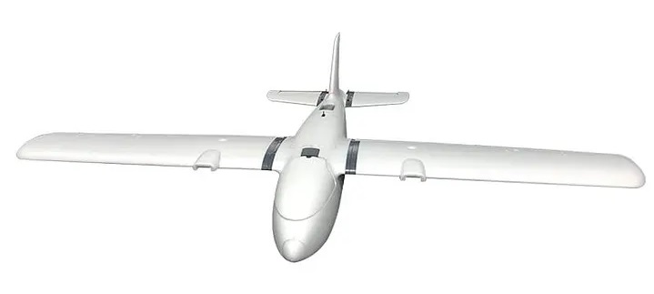
The platform is the MFD Crosswind (also sold as the Nimbus Pro), a 1.9m all-foam twin-motor pusher running ArduPlane 4.0.3 on a Pixhawk Cube Orange, with a Raspberry Pi 3B+ as a companion computer for imaging and path-planning tasks.
Design Decisions
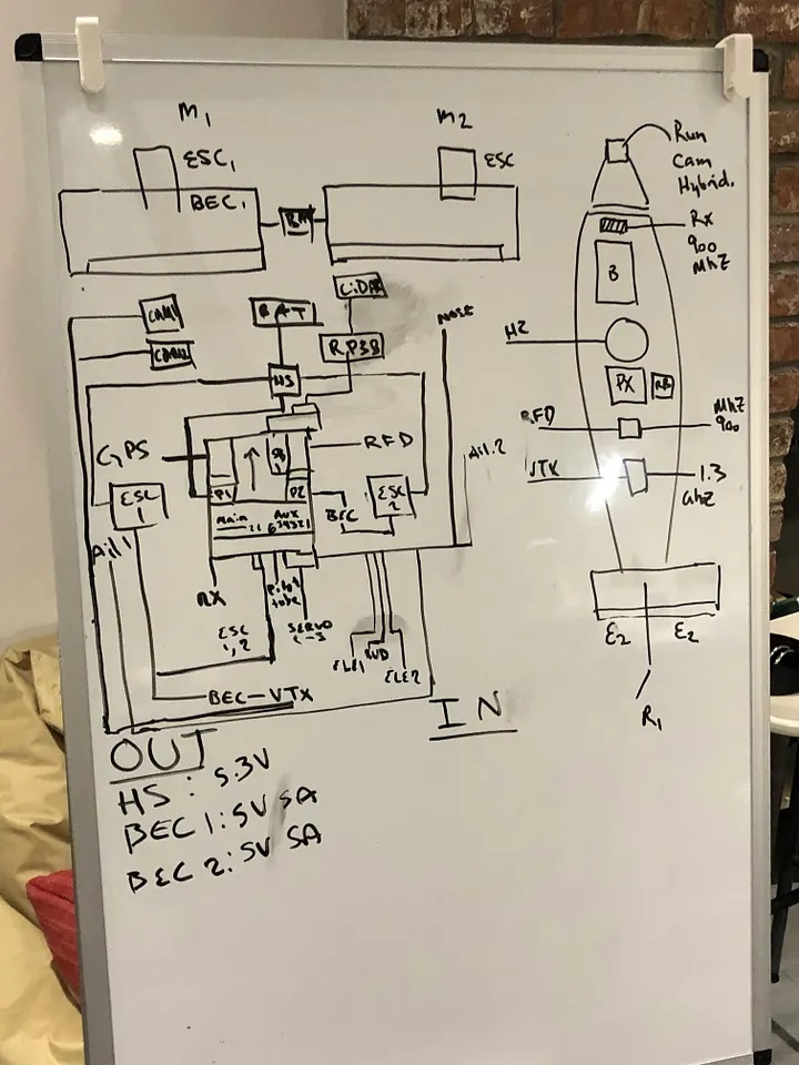
Airframe. The all-foam Crosswind is quick to assemble and cheap to rebuild after crashes, which matters when testing is frequent. Carbon-fiber spars stiffen the wing and fuselage, and XT90 connectors let a wing be swapped after a hard landing. The pusher layout keeps the propellers behind the wing, leaving the nose bay free for the cameras and battery. Propulsion is a pair of SunnySky 2820 800Kv motors turning GWS Slowflyer 8x6 propellers (selected against UIUC propeller performance data), fed from a 6S 6000 mAh LiPo through Hobbywing Skywalker 80A ESCs; each motor draws around 30A at cruise, rising toward 65A under hard acceleration. The tail sits at zero angle of incidence, so level flight needs noticeable up-elevator trim; placing the battery over the wing spars puts the center of gravity about 6.2 cm aft of the leading edge, where the longitudinal pitching moments balance.
Navigation. ArduPlane flies a preprogrammed 3D waypoint course, where each waypoint is a GPS coordinate, an altitude above the home point, and a loiter radius. The course is planned at the ground station and can be updated mid-flight. Airspeed comes from a pitot tube, and a PID attitude loop rejects wind gusts and vibration. The competition scores waypoint capture within 100 ft over the four-mile course. Telemetry runs over a 900 MHz link, and the RTK GPS module supplies the position accuracy the survey grids need.
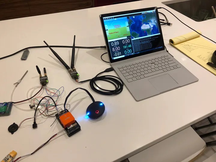
Autonomy. The system handles takeoff, waypoint following, loiter, and return-to-home without operator input. Fail-safes trigger RTH on signal loss, low battery, or geofence breach. The flight controller runs a tuned PID loop for attitude stabilization and L1 navigation for path following.
Imaging. Two cameras split the work. A low-latency Caddx Nebula Pro (720p at 120fps) continuously watches the ground and flags when an object passes beneath, which avoids burning post-processing time on a high-resolution stream. Once flagged, a gimbal-stabilized Sony A6000 (24 MP, 16–50mm lens) captures a high-resolution frame; the gimbal cancels the vibration that would otherwise blur the image at zoom. Frames stream to the ground station over MAVLink to cut post-flight processing, with a copy retained on board as backup.
Object Detection and Localization
Ground targets are one-foot colored squares with a one-inch letter inside, where the square, letter, and background are different colors. When the Nebula Pro flags a target, the corresponding A6000 frame is passed to a Keras sequential model that reads the letter, while color and shape are classified separately. Geolocation is inferred from the aircraft's position along the known flight path (airspeed, course, and elapsed time). The letter, shape, color, and coordinates are stored on the Raspberry Pi 3B+ and streamed to the ground station over MAVLink. The pipeline runs without any request from the ground station, which is the condition the competition rewards as autonomous ODCL.
Airdrop and Ground Vehicle
The payload is a modified LaTrax Teton, a shaft-driven 4WD RC truck chosen for its suspension travel and ground clearance over rough or wet grass. It carries a 16 fl oz mission payload and is lowered under a parachute from at least 150 ft. The suspension is expected to absorb the landing even if the release mechanism fails, and the wide wheelbase lets the vehicle self-right if it lands inverted. After landing it drives autonomously to a target location, carrying its own GPS and autopilot. It is powered by a six-cell NiMH pack through 25A ESCs.
Obstacle Avoidance
Static obstacles are known ahead of time and streamed to the aircraft with their geolocations over the telemetry link; dynamic obstacles require vision. Path planning runs on the Raspberry Pi during flight, consuming the obstacle stream and re-planning around it, with telemetry uploaded at 1 Hz as the competition requires.
Lessons
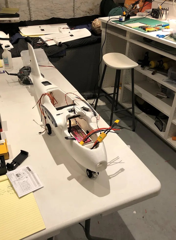
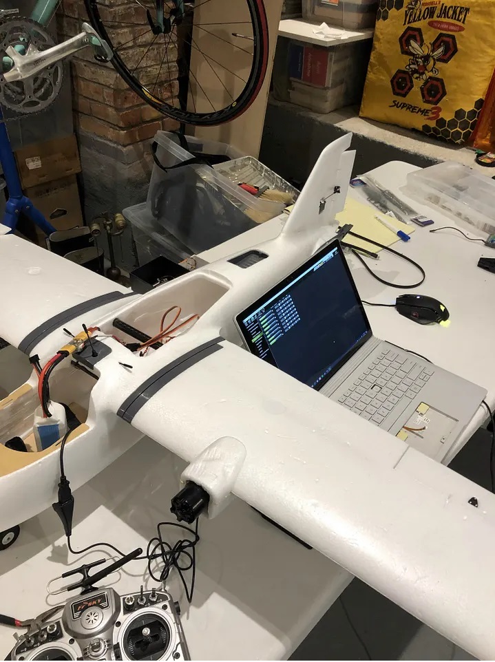
The hardest part of the project was airframe integration: fitting the Pixhawk, Raspberry Pi, GPS, telemetry radio, video transmitter, and two cameras into the foam fuselage while keeping the center of gravity near the 6.2 cm target aft of the leading edge. Weight and CG are the binding constraints because each component addition requires a corresponding ballast adjustment or relocation. The second hardest part was PID tuning in wind, which requires flight time that is expensive in terms of both battery cycles and risk of crashing. The third hardest part was getting the RTK GPS to work reliably in the field.
If I were to revisit the build, the two changes I would prioritize are a cleaner internal layout that decouples payload swaps from CG re-trimming, and a more disciplined tuning process using a simulator (SITL) before committing to flight time. Both are aimed at the same underlying problem: reducing the number of expensive, risk-bearing test flights needed to converge on a working configuration.
Status
As described here the system is a competition design that has been through hardware and software testing rather than a completed competition run; the intent was to demonstrate it at the AUVSI SUAS 2021 event. The specifications above are design choices and bench results, not post-competition measurements.